2016년 6월 21일 화요일

쉽고 저렴한 어린이 용 코딩 교구 소개

몇년 전부터 코딩 교육에 대한 이야기가 많아지고 있습니다.

코딩 교육 소개 영상

이 영상처럼, 아이들에게 코딩을 통한 논리적 사고 능력, 창의력을 키워주고 싶은 데, 방법이 마땅이 떠오르지 않는 경우가 있습니다. 이럴때 학원을 알아보는 경우가 많죠. 사실, 학원도 좋은 방법 중 하나라 생각합니다. 체계적이고 빠른 시간내 무언가를 얻을 수 있습니다. 다만, 비싸고, 지속적인 비용이 들며, 생활과는 분리되어 있죠.

여기서는 생활 속에서 코딩을 저렴하게 체험하고, 가족들과 쉽게 놀 수 있는 몇가지 방법과 교구들을 알아보겠습니다.

1. 몸으로 체험하는 5세 이상 어린이 코딩교구 언플러그드(Unplugged)
몸으로 체험할 수 있도록, 종이, 컵, 색연필 등을 이용해, 코딩을 체험할 수 있는 교구입니다. 컴퓨터 공학의 이론적인 내용들을 모두 몸으로 체험할 수 있도록 교재들을 만들어 놓았기 때문에, 비싼 교구 없이도 아이들에게 코딩 교육을 시켜줄 수 있습니다. 종이, 색연필, 풀, 가위만 있어도 되죠. 필요한 것은 부모님의 열정과 시간입니다.


언플러그드 교구는 주변에서 활용할 수 있는 것들을 사용하기 때문에 누구나 쉽게 체험할 수 있습니다.


언플러그드는 Tim Bell 교수가 만들었으며, http://computingunplugged.org/activities를 방문하시면, 많은 교구와 체험 방법을 무료로 사용할 수 있습니다.


참고로, 한글 교재를 http://www.playsw.or.kr/repo/material 에서 배포하고 있습니다.


2. 3 ~ 6세 어린이를 위한 코딩교구 큐브토(Cubetto) 
스타트업으로 통해 창업한 테크에듀 회사인 Primo Toys의 코딩 교구입니다. 직접 텍스트 방식으로 코딩하지 않아도, 코딩을 통해 논리적 사고력을 키울 수 있도록 되어 있습니다.


로봇을 이동하는 명령 블럭과 함수 블럭을 제공해 다양한 로봇의 움직임을 코딩으로 구현할 수 있습니다.

큐브토 코딩 방식

가격은 225달러이며, 인터넷을 통해 판매하고 있습니다.


3. 5세 이상 어린이와 어른을 위한 전자회로 교구 리틀비츠(little bits)
리틀비츠는 전자회로 교구입니다. 전자회로의 원리를 전혀 몰라도, 납땜이 필요없이, 쉽게 전자회로를 만들고, 재미있는 것들을 만들 수 있는 제품입니다. 마치, 레고블럭 조립하듯이 재미있는 것을 만들 수 있죠.


리틀비츠의 전자회로는 레고블럭 하나에 모터나 LED 등이 하나 붙어 있는 형태로, 각 블럭은 자석이 붙어 있서, 자석으로 블럭이 쉽게 붙게 되어 있습니다. 이때, 회로 연결이 되는 방식이죠. 납땜이 필요없습니다. 그래서, 4~5세 정도 되는 어린이들도 쉽게 전자회로를 만들 수 있습니다. 이런 이유로 교육 용으로 많이 사용되고 있습니다.

리틀비트로 만드는 전자회로 프로젝트 

위 동영상을 보시면 아시겠지만, 레고블록 조립할 수 있는 수준이라면 누구나 따라할 수 있다는 것을 알 수 있습니다 (사실 블록이 많지 않아, 레고블록보다 더 쉽습니다).

가격은 GIZMOS세트가 199.95 달러입니다. 좀 더 자세한 내용은 아래 링크를 참고하시길 바랍니다.

4. 어린이 코딩을 위한 CODE.ORG
CODE.ORG는 코딩 민주화를 위해, 웹사이트에서 접속해서 무료로 코딩을 배울 수 있는 오픈소스 기반 코딩 학습 기부 조직입니다. 다양한 방식의 교구, 튜토리얼 동영상, 교재가 무료로 공유되어 있습니다.


CODE.ORG는 오픈소스 기반이며, 인터넷에서 무료로 코딩을 할 수 있는 거의 모든 교구들을 망라하고 있습니다.


마인크래프트 게임 기반 코딩 (code.org)

대부분의 코딩 교육은 스크래치와 같은 명령 블럭을 조립하거나, 간단한 명령 텍스트를 이용해 학습할 수 있도록 되어 있으며, 코딩한 코드 실행 결과를 화면에서 게임, 그래픽, 소리 등으로 바로 알 수 있도록 되어 있습니다.

5. 어린이 코딩을 위한 스크래치와 엔트리 
스크래치는 MIT에서 개발한 오픈소스 기반 코딩 교구로 어린이가 코딩하여, 게임이나, 아두이노와 같은 피지컬 컴퓨팅을 만들 수 있도록 지원해 주는 SW입니다. 오픈소스로 개발되었기 때문에, 이를 바탕으로 유사한 다양한 코딩 교구 SW가 개발되었으며, 코딩 교육에 큰 영향을 주었습니다.


인터넷에 스크래치와 관련된 수많은 튜토리얼이 있습니다.

스크래치 튜토리얼 영상

국내에서는 스크래치 기반으로 개발된 엔트리가 있습니다. 사용 방법은 거의 동일합니다.

최근에는 스크래치를 이용해, 드론에 명령을 내리는 사례까지 나왔습니다.
스크래치 기반 드론 제어

가격은 무료입니다.

6. 어린이도 손쉽게 만드는 스마트 폰 앱 - 앱 인벤터 
앱 인벤터(App inventor)는 MIT에서 개발한 오픈소스 기반 무료 앱 프로그램 개발 도구로, 인터넷 상에서 앱을 디자인하고 코딩한 후, 본인의 휴대폰에 손쉽게 올릴 수 있습니다. 게임 등 다양한 앱을 만들 수 있고, 관련된 많은 튜토리얼들을 제공합니다.

앱 인벤터 튜토리얼 (MIT App Inventor 유튜브 채널)

만드는 방법은 스크래치와 매우 유사합니다. 어린이도 몇번의 클릭만으로 스마트 폰 앱을 만들 수 있지요. 앱 코딩 순서는 

1. http://ai2.appinventor.mit.edu/ 사이트 접속
2. 팔레트를 이용해 앱 디자인
3. 명령 블록을 이용한 스크래치 코딩
4. 빌드 후 QR코드 링크 생성
5. QR코드 링크로 부터 스마트 폰 앱 설치

팔레트를 이용한 앱 디자인

블록 코딩 모습


앱 빌드 메뉴 실행 후 생성된 QR코드 링크 (QR코드 리더 앱을 이용해 설치할 수 있다)

QR코드 링크로 부터 앱을 설치한 후 스마트 패드에서 실행된 모습 

개발된 앱은 안드로이드 앱이 호환되는 스마트 폰이나 스마트 패드에서 실행될 수 있습니다. 

7. 가상현실 게임 만들기 - CoSpace 
CoSpace는 가상현실 공간을 만드는 도구로 무료입니다. 스크래치와 비슷한 블록 코딩 언어를 이용해, 가상의 공간에서 객체를 만들고, 이벤트에 따라 동작하는 게임을 만들 수 있습니다.

CoSpace의 블록 코딩은 Blocky를 이용합니다. 단순히, 객체를 선택하고, 이름(Tag)를 짓고, 이벤트가 발생하면, 객체를 움직이는 식의 명령 블록을 이용해 쉽게 인터렉티브한 가상공간을 만들 수 있습니다. 
CoSpace의 Blocky를 이용한 코딩
또한, VR, 360 파노라마 뷰 등 다양한 기능이 있어, Google Cardboard와 같은 저렴한 가상현실 헤드셋마운트를 이용해, VR을 체험할 수 있습니다. 


이외에 드론 움직임을 코딩으로 할 수 있는 코드론(CoDrone), 사물의 모든 것을 스위치로 만들어 스크래치로 사물과 반응하는 게임을 만들 수 있는 메이키 메이키(makey makey), 종이에 그리는 전자회로 만들기 Circuit Scribe 등 어린이들이 재미있게 할 수 있는 다양한 코딩 도구들이 있습니다.

드론을 코딩하자! CoDrone

게임을 코딩하자! KUDU

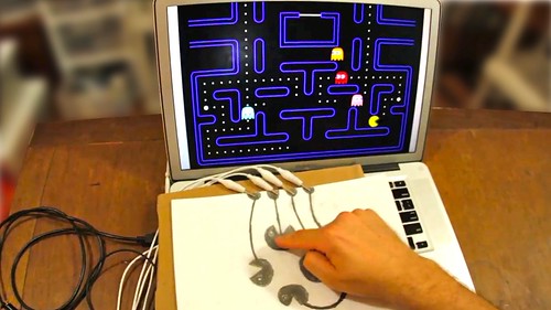
모든 만물을 스위치처럼. 메이키 메이키


종이에 그리는 전자 회로 Circuit Scribe

아두이노 등을 이용해, 피지컬 컴퓨팅을 할 때, 회로도를 그려야할 때가 있습니다. 이때 Fritzing 프로그램을 사용하면, 편리하게 회로 디자인 할 수 있습니다. 디자인된 회로는 PCB(printed circuit board. 인쇄회로기판)로 만들 수 있습니다.

전자회로를 만들고, 전원이 연결되었을 때 시뮬레이션을 미리 해보는 프로그램도 있습니다. Autodesk에서 서비스하는 https://circuits.io/ 은 아두이노와 같은 소형 임베디드 컴퓨터의 코드까지도 가상으로 실행하여, 연결된 전자회로를 시뮬레이션할 수 있습니다. 아울러, 유명한 전자회로나 키트를 지원하고, 만든 것을 공유할 수 있어 사용이 편리합니다.

이외에도 전자회로 디자인과 시뮬레이션을 지원하는 DCACLAB (https://dcaclab.com/ko/home) 가 있습니다. 이 프로그램은 전류의 흐름 등 전자회로 동작을 좀 더 직관적으로 보여줍니다.

이외, 아래와 같은 어린이를 위한 무료 코딩 도구 레퍼런스를 참고하시길 바랍니다.
이런 교구들은 부모님들이 잘 활용한다면, 충분히 저렴하며, 지속적이고, 재미있는 것들을 만들 수 있습니다. 아울러, 이런 교구들이 오픈소스를 바탕으로 한 것이 많아, 많은 튜토리얼과 동작 방식을 얻을 수 있습니다.

다만, 이런 교구들을 사 놓고, 장난감처럼 아이들에게 던져 주기만 하면, 집에서 코딩 교육은 지속되기 어려울 것입니다. 몇번 재미있게 하다가 일주일 지나면 지루해져서, 장난감 상자에 던져 버리겠죠.

사실 교육은 놀이부터 시작된다고 생각합니다. 부모님이 지속적으로 아이에게 관심을 가져주고, 코딩 놀이와 교육에 함께 참여하고, 커뮤니티에 참여해 아이들이 서로 어울릴 수 있도록 노력하는 것이 매우 중요할 것입니다.

2016년 6월 18일 토요일

다양한 센서 마운팅이 가능한 아두이노 기반 무선 제어 4WD 메카넘휠 로버 개발

이 글은 3차원 이미지 스캔 및 역설계 연구와 관련해, 3차원 이미지 스캔 센서 등을 마운팅할 수 있는 무선 제어 로버(rover) 개발에 관한 간단한 글이다.

1. 개요
이 글에서 사용한 로버 프레임은 4WD Mecanum Wheel Kit 이다. 이 프레임에는 아두이노 328이 포함되어 있어, 동작 방식을 코딩 할 수 있다. 이 키트 프레임의 특징은 다음과 같다.
  • 메카넘휠 특징상 몸체를 회전하지 않고, 좌우 및 대각선 방향 이동이 가능하다
  • 몸체가 크게 흔들리지 않고 이동하며, 좁은 장소 이동에 유리하다
  • 속도가 빠르지는 않으나, 무거운 물체를 안정적으로 옮길때 좋다
  • 아두이노 기반 제어라, 개발 편의성과 확장성이 있다
  • 바닥이 고른 곳이나 실내에 맞다
자세한 내용은 다음 사이트를 참고한다.
관련 사이트에는 다음과 같이, 개발에 필요한 기본 코드 등을 제공하고 있다.

pdf icon
570.9KB
4WD-60mm-Mecanum-Wheel-Robot-Kit-10021
jpg icon
610.3KB
Diagram_Mecanum4WD_V4.1
zip icon
61.5KB
Nexus Automation 10021 Library Files
ino icon
1.4KB
RB0021_Omni4WD_PID


2. 로버 제어 코드 업로드
로버 제어를 위해 제공되는 Nexus Automation 10021 Library Files에는 샘플파일이 포함되어 있다. 이를 이용해 로버 제어 코드를 개발하기 위해서는 몇가지 사전 준비가 필요하다.

1. Arduino IDE 1.0.4 다운로드 및 설치: 최신 아두이노 IDE 프로그램은 이 로버에 포함되어 있는 Arduino 328과 호환되지 않는다. 그래서, 오래된 버전을 사용해야 한다.
2. RS485 점퍼 제거: 아두이노 IDE에서 개발된 코드를 Arduino 328 보드에 전송하려면, 다음 그림의 아두이노 입출력 확장 보드의 RS485 점퍼를 제거해야 한다.


구글링을 통해, Arduino 포럼에서 점퍼가 다음 적색 박스에 있다는 것을 확인하였으나, 정확한 위치가 표시되어 있지는 않았다. 해당 점퍼를 제대로 제거하지 않으면, 코드가 전송되지 않는다.

RS485 점퍼들

할 수없이 무한조합을 통해, 다음과 같이 점퍼가 세팅되어 있을 때 코드가 제대로 보드에 업로드된다는 것을 확인하였다.

RS485 점퍼는 바로 앞 그림 속의 3개 점퍼 중 맨 위에 있는 것임 

3. Arduino IDE의 Arduino Duemilanove w/ ATmega328 설정: IDE에서 호환보드로 Arduino Duemilanove w/ ATmega328 를 다음 그림과 같이 설정해야 한다.


3. 로버 제어 코드 분석
로버 제어에 사용되는 라이브러리는 다음과 같이 구성되어 있다.

  • EEPROM: EEPROM에 데이터를 읽고 쓴다.
  • Firmata
  • MotorWheel: Motor wheel을 제어한다.
  • PID_Beta6: PID계산을 수행한다.
  • PinChangeInt: 아두이노 인터럽트 지원을 위한 확장 라이브러리이다.
  • Wire: TWI/I2C 라이브러리이다.

로버 제어 메인 코드는 다음과 같다.

#include <PinChangeInt.h>
#include <PinChangeIntConfig.h>
#include <EEPROM.h>
#define _NAMIKI_MOTOR //for Namiki 22CL-103501PG80:1
#include <fuzzy_table.h>
#include <PID_Beta6.h>
#include <MotorWheel.h>
#include <Omni4WD.h>

#include <fuzzy_table.h>
#include <PID_Beta6.h>

irqISR(irq1,isr1);
MotorWheel wheel1(3,2,4,5,&irq1);

irqISR(irq2,isr2);
MotorWheel wheel2(11,12,14,15,&irq2);

irqISR(irq3,isr3);
MotorWheel wheel3(9,8,16,17,&irq3);

irqISR(irq4,isr4);
MotorWheel wheel4(10,7,18,19,&irq4);

Omni4WD Omni(&wheel1,&wheel2,&wheel3,&wheel4);

void setup() {
//TCCR0B=TCCR0B&0xf8|0x01;    // warning!! it will change millis()
TCCR1B=TCCR1B&0xf8|0x01;      // Pin9,Pin10 PWM 31250Hz
TCCR2B=TCCR2B&0xf8|0x01;      // Pin3,Pin11 PWM 31250Hz
    
Omni.PIDEnable(0.31,0.01,0,10);
}

void loop() {
  // Omni.demoActions(100,1500,500,false);    
}

순서는 다음과 같다.

1. 각 바퀴(MotorWheel) 객체 별로 PWM, Dir, IRQ(interrupt request), ISR(interrupt service routine) 을 설정한다.
2. 각 바퀴 객체를 Omni4WD 객체에 설정한다.
3. setup() 함수에서 메카넘 휠 제어를 위한 PID 값을 설정한다.
4. loop() 함수에서 demo 동작을 수행한다.

각 바퀴를 제어하는 것은 Omni4WD 객체이다. 객체의 클래스 멤버는 다음과 같다.

Omni4WD(MotorWheel* wheelUL,MotorWheel* wheelLL,
MotorWheel* wheelLR,MotorWheel* wheelUR,unsigned int wheelspan=WHEELSPAN);
unsigned char switchMotors();
unsigned char switchMotorsReset();

unsigned int setMotorAll(unsigned int speedMMPS=0,bool dir=DIR_ADVANCE);
unsigned int setMotorAllStop();
unsigned int setMotorAllAdvance(unsigned int speedMMPS=0);
unsigned int setMotorAllBackoff(unsigned int speedMMPS=0);
unsigned int setCarStop(unsigned int ms=0);

int setCarMove(int speedMMPS,float rad,float omega=0);
int setCarAdvance(int speedMMPS=0);
int setCarBackoff(int speedMMPS=0);
int setCarLeft(int speedMMPS=0);
int setCarRight(int speedMMPS=0);

float setCarRotate(float omega);
int setCarRotateLeft(int speedMMPS=0);
int setCarRotateRight(int speedMMPS=0);

int setCarUpperLeft(int speedMMPS=0);
int setCarLowerLeft(int speedMMPS=0);
int setCarUpperRight(int speedMMPS=0);
int setCarLowerRight(int speedMMPS=0);

float getCarSpeedRad() const;
int getCarSpeedMMPS() const;
int setCarSpeedMMPS(int speedMMPS=0,unsigned int ms=1000);
int setCarSlow2Stop(unsigned int ms=1000);

int wheelULGetSpeedMMPS() const;
unsigned int wheelULSetSpeedMMPS(unsigned int speedMMPS,bool dir);
int wheelULSetSpeedMMPS(int speedMMPS);
int wheelLLGetSpeedMMPS() const;
unsigned int wheelLLSetSpeedMMPS(unsigned int speedMMPS,bool dir);
int wheelLLSetSpeedMMPS(int speedMMPS);
int wheelURGetSpeedMMPS() const;
unsigned int wheelURSetSpeedMMPS(unsigned int speedMMPS,bool dir);
int wheelURSetSpeedMMPS(int speedMMPS);
int wheelLRGetSpeedMMPS() const;
unsigned int wheelLRSetSpeedMMPS(unsigned int speedMMPS,bool dir);
int wheelLRSetSpeedMMPS(int speedMMPS);

bool PIDEnable(float kc=KC,float taui=TAUI,float taud=TAUD,unsigned int interval=1000);
bool PIDDisable(); // 201209
bool PIDGetStatus(); // 201209
float PIDGetP_Param(); // 201210
float PIDGetI_Param(); // 201210
float PIDGetD_Param(); // 201210
bool PIDRegulate();
void delayMS(unsigned int ms=100, bool debug=false,unsigned char* actBreak = 0);
void demoActions(unsigned int speedMMPS=100,unsigned int duration=5000,unsigned int uptime=500,bool debug=false);

이 중에 demoActions()함수가 데모 동작 제어를 하는 멤버이다. 이 함수를 좀 더 분석해 보자.

void Omni4WD::demoActions(unsigned int speedMMPS,unsigned int duration,
unsigned int uptime,bool debug) 
{
        // 데모 동작을 위한 함수 포인트 배열 설정. 차례대로, 전진, 후진, 좌로 이동, 우로 이동, 좌상단, 우하단
        // 좌하단, 우상단, 좌회전, 우회전 함수로 구성되어 있다.
int (Omni4WD::*carAction[])(int speedMMPS)={
&Omni4WD::setCarAdvance,
&Omni4WD::setCarBackoff,
&Omni4WD::setCarLeft,
&Omni4WD::setCarRight,
&Omni4WD::setCarUpperLeft,
&Omni4WD::setCarLowerRight,
&Omni4WD::setCarLowerLeft,
&Omni4WD::setCarUpperRight,
&Omni4WD::setCarRotateLeft,
&Omni4WD::setCarRotateRight
};  

        // 각 함수 포인트를 호출하고, 잠시 딜레이를 준다 (데모에서 호출된 시간은 1.5초이므로, 
        // 이 시간 동안, 각 함수 기능이 수행된다.
for(int i=0;i<10;++i) {
(this->*carAction[i])(0); // default parameters not available in function pointer
setCarSpeedMMPS(speedMMPS, uptime);
delayMS(duration, debug);
setCarSlow2Stop(uptime);  // 다음 동작 전에 천천히 멈춘다. 데모는 0.5초 동안이다. 
}
setCarStop();               // 완전히 멈춘다.
delayMS(duration);       // 지연을 둔다. 데모는 1.5초이다.
}

4. 로버 제어 동작 제어
로버 제어 코드는 다음과 같다.
이제 로버를 제어하는 주요 함수의 기능을 파악했으니, 간단히, 로버를 1.5초 직진한 후, 좌측으로 1.5초 이동해, 1.5초 멈추고, 다시 원 위치로 오는 동작을 코딩해 보자.

void loop() {
  // 각 함수 포인트를 호출하고, 잠시 딜레이를 준다 (데모에서 호출된 시간은 1.5초이므로, 
  // 이 시간 동안, 각 함수 기능이 수행된다.
  unsigned int speedMMPS = 100;
  unsigned int duration = 1500;
  unsigned int uptime = 500;
  bool debug = false;
  
  for(int i=0; i < 4; ++i) 
  {
    if(i == 0)
      Omni.setCarAdvance(0);
    else if(i == 1)
      Omni.setCarLeft(0);
    else if(i == 2)
      Omni.setCarRight(0);
    else
      Omni.setCarBackoff(0);

    Omni.setCarSpeedMMPS(speedMMPS, uptime);
    Omni.delayMS(duration, debug);
    Omni.setCarSlow2Stop(uptime);  // 다음 동작 전에 천천히 멈춘다. 데모는 0.5초 동안이다. 
  }
  
  Omni.setCarStop();            // 완전히 멈춘다.
  Omni.delayMS(duration);       // 지연을 둔다. 데모는 1.5초이다.    
}

이제 앞에처럼, 코딩한 것을 로버에 전송해 본다. 그리고, 로버의 파워 버튼을 눌러 본다. 다음과 같이 동작되면, 성공한 것이다.


5. 로버 무선 제어 
로버 무선 제어를 위해, 아두이노 확장 보드에 있는 Bluetooth 무선 통신 핀을 사용해 보자. 확장보드의 재원은 다음 링크를 참고한다.


사실, 이 확장보드 사용방법은 그리 친절하지 않다. 블루투스 통신을 위해서는 우선 HC-06같은 블루투스 통신 장치가 있어야 하며, 통신 속도 등을 미리 설정해 놓어야 한다. 이 경우에는 AT+BAUD8 명령으로 최고속도로 설정해 놓고, 아두이노 보드에서 시리얼 통신으로 정상 설정되었는 지 등을 여러번 테스트해 보는 과정을 거쳤다.

이제, 블루투스 통신 장치의 이름, 속도(115200), 암호(보통은 1234임) 등이 제대로 확인되었다면, 다음과 같은 순서로 로버 무선 통신을 개발해본다.

1. 다음과 같이 코딩하여, 로버의 아두이노 보드에 전송한다. 로버 컨트롤 코딩은 매우 간단하게, g(go), back(b), left(l), right(r), t1(turn left), t2(turn right)로 하였다.

#include <PinChangeInt.h>
#include <PinChangeIntConfig.h>
#include <EEPROM.h>
#define _NAMIKI_MOTOR //for Namiki 22CL-103501PG80:1
#include <fuzzy_table.h>
#include <PID_Beta6.h>
#include <MotorWheel.h>
#include <Omni4WD.h>

#include <fuzzy_table.h>
#include <PID_Beta6.h>

// #include <SoftwareSerial.h>
// SoftwareSerial mySerial(10, 11); // RX, TX

irqISR(irq1,isr1);
MotorWheel wheel1(3,2,4,5,&irq1);

irqISR(irq2,isr2);
MotorWheel wheel2(11,12,14,15,&irq2);

irqISR(irq3,isr3);
MotorWheel wheel3(9,8,16,17,&irq3);

irqISR(irq4,isr4);
MotorWheel wheel4(10,7,18,19,&irq4);


Omni4WD Omni(&wheel1,&wheel2,&wheel3,&wheel4);

boolean toggle = false;
void toggleLED()
{
  if(toggle == false)
    digitalWrite(13, HIGH);
  else
    digitalWrite(13, LOW);
  toggle = toggle ? false : true;
}

void setup() {
  //TCCR0B=TCCR0B&0xf8|0x01;    // warning!! it will change millis()
  TCCR1B=TCCR1B&0xf8|0x01;    // Pin9,Pin10 PWM 31250Hz
  TCCR2B=TCCR2B&0xf8|0x01;    // Pin3,Pin11 PWM 31250Hz

  Omni.PIDEnable(0.31,0.01,0,10);
  
  Serial.begin(115200);
  pinMode(13, OUTPUT);   
}

void loop() {
  // Omni.demoActions(100,1500,500,false);
  
  char val = 0;
  char string[256];
  int i = 0;
  while(Serial.available())
  {
    char ch = Serial.read();
    string[i] = ch;
    i++;
    if(ch == -1)
      break;
    delay(5);
  }
  string[i] = 0;


  unsigned int speedMMPS = 100;
  unsigned int duration = 1000;
  unsigned int uptime = 500;
  bool debug = false;

  if(strstr(string, "g"))
  {
    Omni.setCarAdvance(0);  
    Omni.setCarSpeedMMPS(speedMMPS, uptime);
    Omni.delayMS(duration, debug);
    Omni.setCarSlow2Stop(uptime);  
  }
  else if(strstr(string, "b"))
  {
    Omni.setCarBackoff(0);
    Omni.setCarSpeedMMPS(speedMMPS, uptime);
    Omni.delayMS(duration, debug);
    Omni.setCarSlow2Stop(uptime);  
  }
  else if(strstr(string, "l"))
  {
    Omni.setCarLeft(0);
    Omni.setCarSpeedMMPS(speedMMPS, uptime);
    Omni.delayMS(duration, debug);
    Omni.setCarSlow2Stop(uptime); 
  }
  else if(strstr(string, "r"))
  {
    Omni.setCarRight(0);
    Omni.setCarSpeedMMPS(speedMMPS, uptime);
    Omni.delayMS(duration, debug);
    Omni.setCarSlow2Stop(uptime); 
  }
  else if(strstr(string, "t1"))
  {
    Omni.setCarRotate(0);
    Omni.setCarRotateLeft(speedMMPS);
    Omni.delayMS(duration, debug);
    Omni.setCarSlow2Stop(uptime);  
  }
  else if(strstr(string, "t2"))
  {
    Omni.setCarRotate(0);
    Omni.setCarRotateRight(speedMMPS);
    Omni.delayMS(duration, debug);
    Omni.setCarSlow2Stop(uptime);
  }
  else if(strstr(string, "t"))
  {
    toggleLED();
  }
  
  Omni.setCarStop();            // 완전히 멈춘다. 
  Omni.delayMS(duration);    // 지연을 둔다. 데모는 1.5초이다.  
}

2. 확장보드의 APC 220/Bluetooth 핀을 본인이 가지고 있는 블루투스 송수신 장치와 연결
확장보드의 해당 핀들 중 RX, TX, VCC, GND만 연결하면 된다.


HC-06 블루투스의 경우, RX, TX, VCC, GND가 있으며, VCC, GND는 같은 핀에 연결하고, RX, TX만 서로 바꾸어 연결한다.

  VCC - VCC
  GND - GND
  RX - TX
  TX - RX

로버에 블루투스를 연결 모습

3. Bluetooth Terminal 앱을 안드로이드 폰이나 스마트 패드에 설치하고, 앞에서 연결한 블루투스와 페어링한 후, 이 앱을 실행해, 연결하고, 글자를 입력하여 테스트해본다. 정상적이면, 다음과 같이 무선으로 로버를 조정할 수 있다.

블루투스 무선 기반 로버 제어 테스트 화면

테스트를 위해, 블루투스 통신이 어렵도록 문을 닫고 테스트를 해 본다던지, 원거리에서 테스트해 보는 등의 과정을 거쳤으나, 큰 문제 없이 잘 동작된다. 보통, 블루투스는 탁 트인곳에서 20미터에서 최대 30미터까지 통신이 가능하다. 물론, 블루투스 통신이 많은 환경에서는 이름, 암호 등은 다르게 설정해야 혼선이 없다.

이제 로버에 무선 통신을 이용해 다양한 명령을 줄 수 있으니, 로버에 마운팅된 센서에서 데이터를 받거나, 액추에이터를 제어할 수 있다. 다만, 대용량 데이터가 필요한 센서의 경우에는 WiFi 등 좀 더 대역폭이 좋은 무선 통신 방식을 사용해야 한다.

다음 영상은 작업자가 진입하기 어려운 공간의 3차원 이미지 스캔을 위해 트림블사의 스캐너를 이 로버와 마운팅해 테스트한 영상이다.

3차원 이미지 스캔 기반 Inspection rover


로버 기반 3차원 이미지 스캐닝 결과

6. 마무리
이 글에서 사용된 로버의 제어 보드는 스펙이 좀 오래된 것이라, 점퍼 등 정확한 제원을 찾기가 어려웠다. 하지만, 가성비가 높고, 메카넘휠이 추가되어 있어, 안정적으로 이동하는 로버를 개발할 수 있다. 아울러, 많은 아두이노 라이브러리를 이용해, 센서와 연동하면, 더 강력한 로버를 개발할 수 있다는 점은 확장성 면에서 큰 장점이다.


원격 야외 이미지 스캔용 캐터필터 타입 로버 개발

이 글은 원격으로  간단한 야외 이미지 스캔 테스트 목적의 캐터필터 타입 로버에 대한 개발 정보를 간단히 정리한 것이다. 본 로버 개발에는 ROS, OpenCM, 로보티즈 다이나믹셀, RGBD센서 등이 사용되었다.

1. 개요
캐터필터 타입은 울퉁불퉁한 지형에서 효과적이고, 매우 빠른 속도로 지형을 주행할 수 있다. 본 글에서 소개하는 캐터필터 타입 로버는 DAGU T'REX 이다.


컨트롤러는 별도로 구입해 설치해야 하는 데, DAGU에서 T'REX controller 로 검색하면 발견할 수 있다.


아두이노 호환 보드라, 코딩이 쉽다. 그리고, 다음과 같이 메뉴얼, 코드, 소프트웨어를 제공한다.
기타 다음 링크를 참고하면 도움이 된다.

2. 소스 코드 분석
제공되는 기본 소스 코드는 아두이노 Arduino Nano w/ 328 보드 용이다. 코드 전체 리스트는 다음과 같다. 크게 setup과 loop로 나눠져 있으며, loop는 진단을 위한 동작 실행 함수(DiagnoticMode), 배터리가 낮을 때 셧다운 모드, RC 모드, 블루투스 모드 등으로 구성되어 있음을 알 수 있다.


#include <Wire.h>                                      // interrupt based I2C library
#include <Servo.h>                                     // library to drive up to 12 servos using timer1
#include <EEPROM.h>                                    // library to access EEPROM memory
#include "IOpins.h"                                    // defines which I/O pin is used for what function

// define constants here
#define startbyte 0x0F                   // for serial communications each datapacket must start with this byte

// define global variables here
byte mode=0;                                           // mode=0: I2C / mode=1: Radio Control / mode=2: Bluetooth / mode=3: Shutdown
int  lowbat=550;                                       // default low battery voltage is 5.5V
byte errorflag;                                        // non zero if bad data packet received
byte pwmfreq;                                          // value from 1-7
byte i2cfreq;                                          // I2C clock frequency can be 100kHz(default) or 400kHz
byte I2Caddress;                                       // I2C slave address
int lmspeed,rmspeed;                                   // left and right motor speeds -255 to +255
byte lmbrake,rmbrake;                                  // left and right brakes - non zero values enable brake
int lmcur,rmcur;                                       // left and right motor current
int lmenc,rmenc;                                       // left and right encoder values
int volts;                                             // battery voltage*10 (accurate to 1 decimal place)
int xaxis,yaxis,zaxis;                                 // X, Y, Z accelerometer readings
int deltx,delty,deltz;                                 // X, Y, Z impact readings 
int magnitude;                                         // impact magnitude
byte devibrate=50;   // number of 2mS intervals to wait after an impact has occured before a new impact can be recognized
int sensitivity=50;                                    // minimum magnitude required to register as an impact

byte RCdeadband=35;                                    // RCsignal can vary this much from 1500uS without controller responding
unsigned long time;                                    // timer used to monitor accelerometer and encoders

byte servopin[6]={7,8,12,13,5,6};                      // array stores IO pin for each servo
int servopos[6];                                       // array stores position data for up to 6 servos
Servo servo[6];                                        // create 6 servo objects as an array

void setup()
{
  //all IO pins are input by default on powerup --------- configure motor control pins for output -------- pwm autoconfigures -----------

  pinMode(lmpwmpin,OUTPUT);                            // configure left  motor PWM       pin for output
  pinMode(lmdirpin,OUTPUT);                            // configure left  motor direction pin for output
  pinMode(lmbrkpin,OUTPUT);                            // configure left  motor brake     pin for output
  
  pinMode(rmpwmpin,OUTPUT);                            // configure right motor PWM       pin for output
  pinMode(rmdirpin,OUTPUT);                            // configure right motor direction pin for output
  pinMode(rmbrkpin,OUTPUT);                            // configure right motor brake     pin for output
  
  //----------------------------------------------------- Test for RC inputs --------------------------------------------
  digitalWrite(RCspeedpin,1);                          // enable weak pullup resistor on input to prevent false triggering                   
  digitalWrite(RCsteerpin,1);                          // enable weak pullup resistor on input to prevent false triggering
  delay(100);
  int t1=int(pulseIn(RCspeedpin,HIGH,30000));          // read throttle/left stick
  int t2=int(pulseIn(RCsteerpin,HIGH,30000));          // read steering/right stick
  if(t1>1000 && t1<2000 && t2>1000 && t2<2000)         // RC signals detected - go to RC mode
  {
    mode=1;                                            // set mode to RC
    MotorBeep(3);                                      // generate 3 beeps from the motors to indicate RC mode enabled
  }
  
  //----------------------------------------------------- Test for Bluetooth module ----------------------------------
  if(mode==0)                                          // no RC signals detected
  {
    BluetoothConfig();                                 // attempts to configure bluetooth module - changes to mode 2 if successful
    if(mode==2) MotorBeep(2);                          // generate 2 beeps from the motors to indicate bluetooth mode enabled
  }
  
  //----------------------------------------------------- Configure for I²C control ------------------------------------
  if(mode==0)                                          // no RC signal or bluetooth module detected
  {
    MotorBeep(1);                                      // generate 1 beep from the motors to indicate I²C mode enabled
    byte i=EEPROM.read(0);                             // check EEPROM to see if I²C address has been previously stored
    if(i==0x55)                                        // B01010101 is written to the first byte of EEPROM memory to indicate that an I2C address has been previously stored
    {
      I2Caddress=EEPROM.read(1);                       // read I²C address from EEPROM
    }
    else                                               // EEPROM has not previously been used by this program
    {
      EEPROM.write(0,0x55);                            // set first byte to 0x55 to indicate EEPROM is now being used by this program
      EEPROM.write(1,0x07);                            // store default I²C address
      I2Caddress=0x07;                                 // set I²C address to default
    }
    
    Wire.begin(I2Caddress);                            // join I²C bus as a slave at I2Caddress
    Wire.onReceive(I2Ccommand);                        // specify ISR for data received
    Wire.onRequest(I2Cstatus);                         // specify ISR for data to be sent
  }
}

void loop()
{
  // DiagnosticMode();

  if (mode==3)                                         // if battery voltage too low
  {
    Shutdown();                                        // Shutdown motors and servos
    return;
  }
  
  //----------------------------------------------------- RC Mode -----------------------------------------------------
  if(mode==1)                                           
  {
    RCmode();                                          // monitor signal from RC receiver and control motors
    return;                                            // I²C, Bluetooth and accelerometer are ignored
  }
  
  //----------------------------------------------------- Bluetooth mode ----------------------------------------------
  if(mode==2)
  {
    Bluetooth();                                       // control using Android phone and sample app
    return;
  }
  
  //----------------------------------------------------- I²C mode -----------------------------------------------------
  static byte alternate;  // variable used to alternate between reading accelerometer and power analog inputs


  //----------------------------------------------------- Perform these functions every 1mS ------------------------
  if(micros()-time>999)                       
  {
    time=micros();                                     // reset timer
    alternate=alternate^1;                             // toggle alternate between 0 and 1
    Encoders();                                        // check encoder status every 1mS

    //-------- These functions must alternate as they both take in excess of 780uS ------------    
    if(alternate)
    {
      Accelerometer();                                 // monitor accelerometer every second millisecond                            
    }
    else 
    {
      lmcur=(analogRead(lmcurpin)-511)*48.83;  // read  left motor current sensor and convert reading to mA
      rmcur=(analogRead(rmcurpin)-511)*48.83; // read right motor current sensor and convert reading to mA
      volts=analogRead(voltspin)*10/3.357; // read battery level and convert to volts with 2 decimal places (eg. 1007 = 10.07 V)
      if(volts<lowbat) mode=3;                // change to shutdown mode if battery voltage too low
    }
  }
}

DiagnoticModel 함수는 좌측, 우측 캐터필러를 회전하도록 코딩되어 있다.

void DiagnosticMode()
{
  //---------------------------------------- Diagnostic Mode ------------------------------------//
  //  This simple routine runs the motors forward / backward and brakes to test the "H" bridges  //
  //  Battery voltage, accelerometer data and motor current draw is displayed on serial monitor  //
  //             When LEDs are connected to servo outputs they will chase in sequence            //
  //---------------------------------------------------------------------------------------------//
  
  static int mdir,mpwm,brk,LED,div;
  if(mdir==0)                             // first time through the loop mdir=0 
  {                                       // initialize diagnostic routine
    mdir=5;                               // motor direction cannot start at 0 or motors will not move   
    for(byte i=0;i<6;i++)                 // scan through servo pins
    {
      pinMode(servopin[i],OUTPUT);        // set servo pin to OUTPUT
    }
  }
  
  mpwm+=mdir;             // motor speed/direction is incremented/decremented by motor direction                   
  if(mpwm<-250 || mpwm>250)               // PWM value must be between -255 and +255
  {
    mdir=-mdir;                           // when limit is reached, reverse direction
    brk=1;                                // engage brake for quick slow down
  }
  if(mpwm==0) brk=0;                      // if motor PWM is 0 then disable the brake - motor can start again
  
  lmspeed=mpwm;                           // set left  motor speed
  rmspeed=mpwm;                           // set right motor speed
  lmbrake=brk;                            // enable / disable left  brake
  rmbrake=brk;                            // enable / disable right brake
  Motors();                               // update speed, direction and brake of left and right motors
  
  div++;                                  // divider used to slow down LED chasing
  if(div>20)
  {
    div=0;                                // reset divider
    LED++;                                // increment LED chase sequence
  }
  
  if(LED>5) LED=0;                        // cause chase sequence to repeat
  for(byte i=0;i<6;i++)                   // scan servo control pins
  {
    digitalWrite(servopin[i],LED==i);     // drive LEDs in chase sequence
  }
  
  Serial.print("Battery voltage: "); Serial.print(int(analogRead(voltspin)*10/3.357));Serial.print("\t");
  
  Serial.print("X: "); Serial.print(analogRead(axiszpin));Serial.print("\t");
  Serial.print("Y: "); Serial.print(analogRead(axisypin));Serial.print("\t");
  Serial.print("Z: "); Serial.print(analogRead(axisxpin));Serial.print("\t");
  
  lmcur=(analogRead(lmcurpin)-511)*48.83;
  rmcur=(analogRead(rmcurpin)-511)*48.83;
  Serial.print("Lmotor current: ");Serial.print(lmcur);Serial.print("mA\t");
  Serial.print("Rmotor current: ");Serial.print(rmcur);Serial.print("mA\t");
  Serial.print("PWM:");Serial.println(mpwm);
  delay(10);
}

코드를 분석하면, 알겠지만, 왼쪽, 오른쪽 회전에 관련된 전역변수인 lmspeed, rmspeed가 있으며, 여기에 속도를 넣고, Motors() 함수를 호출하면, 좌/우측 캐터필터가 회전하도록 되어 있음을 확인할 수 있다. 이는 블루투스 무선 통신 기반으로 동작을 제어하는 코드도 유사하다. 아래 블루투스 무선 통신 제어 코드는 속도를 앱으로 부터 전달받아, Motors() 함수를 호출한다.

void Bluetooth()
{
  static byte d,e;                                             // data and error bytes
  if(Serial.available()>2)                                     // Command is 3 bytes in length
  {
    d=Serial.read();                                           // read byte from buffer
    if(d!=startbyte)                                           // if byte is not a start byte (0x0F)
    {
      lmspeed=0;                                               // bad data received
      rmspeed=0;                                               // set motor speeds to 0
      e=0;                                                     // error flag reset
    }
    else
    {
      lmspeed=(int(Serial.read())-127)*2-1;                    // good data received
      rmspeed=(int(Serial.read())-127)*2-1;                    // read values for left and right motors
    }
  }
  else                                                         // less than 3 bytes in buffer
  {
    e++;                                                       // count program loops with less than 3 bytes in buffer
    if(e>100)                                        // assume lost signal if buffer less than 3 bytes for too long
    {
      lmspeed=0;                                               // stop left motor
      rmspeed=0;                                               // stop right motor
      e=0;                                                     // reset error counter
    }
  }
  Motors();                                                    // update motors 
}

블루투스 통신을 위해서, Serial 포트를 초기화해주어야 한다. 이는 mode란 전역변수가 0일 경우, 자동으로 컨트롤보드에 블루투스 장치가 있는 지 체크하고, 있으면 통신 속도 등을 기본으로 설정해 블루투스 컨트롤 모드임을 mode = 2로 표시한다. 다만, HC-06 블루투스 장치를 사용할 때는, 이 코드가 제대로 동작하지 않는다. 

void BluetoothConfig()  // This code intended for a DAGU bluetooth module - may not work with other 
{
  long baud[]={9600,115200,57600,38400,19200,4800,2400,1200};  // try 9600 first as this is default setting then try other baud rates
  byte br=0,d;
  while(mode==0 && br<8)                                       // scan through different baud rates and attempt to configure bluetooth module
  {
    Serial.begin(baud[br]);                                    // enable T'REX serial at baud rate baud[br]
    Serial.print("AT");                                        // send "AT" to see if bluetooth module is connected
   
    if(Serial.available()>1)                                   // after 1 second the bluetooth module should respond
    {
      byte i=Serial.read();                                    // should be 79 "O"
      delay(3);      
      byte j=Serial.read();                                    // should be 75 "K"
      if(i==79 && j==75)                                       // if response is "OK" then cofigure bluetooth module
      {
        EmptyBuffer();                                         // clear buffer
        Serial.print("AT+NAMET'REX");                          // ensure name is set to "T'REX"
        delay(1500);                                           // wait for bluetooth module to respond
        EmptyBuffer();                                         // clear buffer
        Serial.print("AT+PIN1234");                            // ensure PIN is set to "1234"
        delay(1500);                                           // wait for bluetooth module to respond
        EmptyBuffer();                                         // clear buffer
        if(br!=0)                                              // if bluetooth baud rate was not 9600
        { 
          Serial.print("AT+BAUD4");                            // set bluetooth baud rate to 9600
          delay(1500);                                         // wait for bluetooth module to respond
          EmptyBuffer();                                       // clear buffer
          Serial.end();                                        // close serial communications at current baud rate
          Serial.begin(9600);                                  // set T'REX controller serial communications to 9600
        }
        mode=2;                                                // bluetooth module successfully detected and configured - change to bluetooth mode
      }        
    }
    if(mode==0)                                                // bad response - bluetooth module not communicating at current baud rate
    {
      EmptyBuffer();
      Serial.end();                                            // close serial communications at this baud rate
      br++;                                                    // prepare to try next baud rate
    }
  } 

}

이런 이유로, HC-06과 같은 블루투스 장치의 경우에는 다음과 같이 코딩하여, 강제로 Serial 포트를 초기화하도록 한다.

void BluetoothConfig()  
{
  Serial.begin(9600);      // set T'REX controller serial communications to 9600
  Serial.flush();
  mode=2;           // bluetooth module successfully detected and configured - change to bluetooth mode

  delay(1500); 
}

모터 제어 코드는 다음과 같이 간단하다.

void Motors()
{
  digitalWrite(lmbrkpin,lmbrake>0);        // if left brake>0 then engage electronic braking for left motor
  digitalWrite(lmdirpin,lmspeed>0);        // if left speed>0 then left motor direction is forward else reverse
  analogWrite (lmpwmpin,abs(lmspeed));    // set left PWM to absolute value of left speed - if brake is engaged then PWM controls braking

  if(lmbrake>0 && lmspeed==0) lmenc=0;   // if left brake is enabled and left speed=0 then reset left encoder counter
  
  digitalWrite(rmbrkpin,rmbrake>0);       // if right brake>0 then engage electronic braking for right motor
  digitalWrite(rmdirpin,rmspeed>0);       // if right speed>0 then right motor direction is forward else reverse
  analogWrite (rmpwmpin,abs(rmspeed));  // set right PWM to absolute value of right speed - if brake is engaged then PWM controls braking

  if(rmbrake>0 && rmspeed==0) rmenc=0;   // if right brake is enabled and right speed=0 then reset right encoder counter
}

이 코드를 아두이노 기반 로버 컨트롤러에 업로드하면, 다음과 같이 정상 작동하는 것을 확인할 수 있다.


3. 무선 제어
이제 무선 제어를 위해 블루투스를 연결한다. 여기서는 HC-06을 사용하였다. 다만, 블루투스를 컨트롤러와 연결할 때, RX, TX를 서로 엊갈려 연결해야 정상적으로 동작한다.


연결할 블루투스가 검색되면, 자동으로 baud rate은 9600, 이름은 T'REX, 핀 번호는 1234로 설정된다. 앞서 언급했듯이 HC-06을 사용하면, 미리 속도와 이름을 9600, T'REX 이렇게 설정하도록 한다. 설정 프로그램은 헤라클래스(hercules setup utility by hw-group.com) 프로그램을 사용하였다(여기서 다운로드 가능하다). 블루투스는 앞에 링크에 있는 안드로이드 앱과 연동되어, 로버를 컨트롤한다.

이제 테스트해보면, 다음과 같이 잘 동작됨을 알 수 있다.


이제 센서를 부착하고, 센서 데이터를 처리해 WiFi로 노트북의 ROS master에 전송할 수 있도록 TK1 보드를 설치한다. 사실, 개발 시간이 매우 부족한 관계로 아직 컨트롤보드와 TK1을 통합하지는 못하였다. 센서와 마운트는 로보티즈의 다이나믹셀을 사용하였다. 참고로, 미리 디자인되지 않은 범용 DIY 부품을 쓰다보면, 부품이나 전선 배치가 기성품처럼 깔끔하지 못하다. 그래서, 가능한 연구 목적에 필요한 부품을 수용할 수 있는 프레임을 사용하는 것이 좋다.


다음은 실제로 3차원 이미지 센서를 부착해, 야외에서 테스트해 본 영상이다. 야외는 케이블들이 아스팔트, 콘트리트 바닥에 흩어져 있고, 사람이 진입하기 어려울 설비 박스가 있다.


다음은 실시간으로 로버로 부터 센서 데이터를 취득한 결과 영상이다.


영상에서 보는 바와 같이, 무선으로 제어하고, 센서로 2D, 3D 이미지를 취득할 수 있으므로, 사람이 진입하기 어려운 곳에 활용하기 좋다.


4. 마무리
여기서 사용한 TRex 캐터필러 로버는 야외 동작에 맞게, 모터 토크가 강하고, 프레임이 매우 단단하다. 아울러, 캐터필러가 금속으로 되어 있어, 험한 지형에서도 주행이 안정적이고 원활하다. 그래서, 야외에서 인스펙션이 필요한 센서를 마운팅하고 탐색하기가 좋다.