1. 개요
캐터필터 타입은 울퉁불퉁한 지형에서 효과적이고, 매우 빠른 속도로 지형을 주행할 수 있다. 본 글에서 소개하는 캐터필터 타입 로버는 DAGU T'REX 이다.
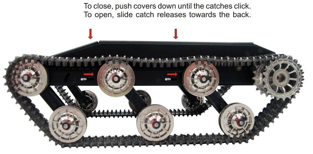
컨트롤러는 별도로 구입해 설치해야 하는 데, DAGU에서 T'REX controller 로 검색하면 발견할 수 있다.
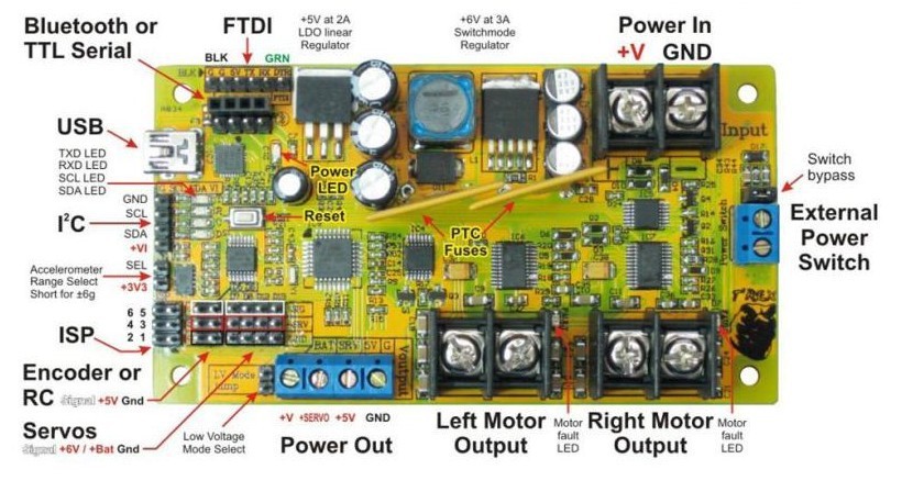
아두이노 호환 보드라, 코딩이 쉽다. 그리고, 다음과 같이 메뉴얼, 코드, 소프트웨어를 제공한다.
- Manual:download link (direct download link)
- Code:download link
- SOFTWARE:download Link
- Android App: download Link
2. 소스 코드 분석
제공되는 기본 소스 코드는 아두이노 Arduino Nano w/ 328 보드 용이다. 코드 전체 리스트는 다음과 같다. 크게 setup과 loop로 나눠져 있으며, loop는 진단을 위한 동작 실행 함수(DiagnoticMode), 배터리가 낮을 때 셧다운 모드, RC 모드, 블루투스 모드 등으로 구성되어 있음을 알 수 있다.
#include <Wire.h> // interrupt based I2C library
#include <Servo.h> // library to drive up to 12 servos using timer1
#include <EEPROM.h> // library to access EEPROM memory
#include "IOpins.h" // defines which I/O pin is used for what function
// define constants here
#define startbyte 0x0F // for serial communications each datapacket must start with this byte
// define global variables here
byte mode=0; // mode=0: I2C / mode=1: Radio Control / mode=2: Bluetooth / mode=3: Shutdown
int lowbat=550; // default low battery voltage is 5.5V
byte errorflag; // non zero if bad data packet received
byte pwmfreq; // value from 1-7
byte i2cfreq; // I2C clock frequency can be 100kHz(default) or 400kHz
byte I2Caddress; // I2C slave address
int lmspeed,rmspeed; // left and right motor speeds -255 to +255
byte lmbrake,rmbrake; // left and right brakes - non zero values enable brake
int lmcur,rmcur; // left and right motor current
int lmenc,rmenc; // left and right encoder values
int volts; // battery voltage*10 (accurate to 1 decimal place)
int xaxis,yaxis,zaxis; // X, Y, Z accelerometer readings
int deltx,delty,deltz; // X, Y, Z impact readings
int magnitude; // impact magnitude
byte devibrate=50; // number of 2mS intervals to wait after an impact has occured before a new impact can be recognized
int sensitivity=50; // minimum magnitude required to register as an impact
byte RCdeadband=35; // RCsignal can vary this much from 1500uS without controller responding
unsigned long time; // timer used to monitor accelerometer and encoders
byte servopin[6]={7,8,12,13,5,6}; // array stores IO pin for each servo
int servopos[6]; // array stores position data for up to 6 servos
Servo servo[6]; // create 6 servo objects as an array
void setup()
{
//all IO pins are input by default on powerup --------- configure motor control pins for output -------- pwm autoconfigures -----------
pinMode(lmpwmpin,OUTPUT); // configure left motor PWM pin for output
pinMode(lmdirpin,OUTPUT); // configure left motor direction pin for output
pinMode(lmbrkpin,OUTPUT); // configure left motor brake pin for output
pinMode(rmpwmpin,OUTPUT); // configure right motor PWM pin for output
pinMode(rmdirpin,OUTPUT); // configure right motor direction pin for output
pinMode(rmbrkpin,OUTPUT); // configure right motor brake pin for output
//----------------------------------------------------- Test for RC inputs --------------------------------------------
digitalWrite(RCspeedpin,1); // enable weak pullup resistor on input to prevent false triggering
digitalWrite(RCsteerpin,1); // enable weak pullup resistor on input to prevent false triggering
delay(100);
int t1=int(pulseIn(RCspeedpin,HIGH,30000)); // read throttle/left stick
int t2=int(pulseIn(RCsteerpin,HIGH,30000)); // read steering/right stick
if(t1>1000 && t1<2000 && t2>1000 && t2<2000) // RC signals detected - go to RC mode
{
mode=1; // set mode to RC
MotorBeep(3); // generate 3 beeps from the motors to indicate RC mode enabled
}
//----------------------------------------------------- Test for Bluetooth module ----------------------------------
if(mode==0) // no RC signals detected
{
BluetoothConfig(); // attempts to configure bluetooth module - changes to mode 2 if successful
if(mode==2) MotorBeep(2); // generate 2 beeps from the motors to indicate bluetooth mode enabled
}
//----------------------------------------------------- Configure for I²C control ------------------------------------
if(mode==0) // no RC signal or bluetooth module detected
{
MotorBeep(1); // generate 1 beep from the motors to indicate I²C mode enabled
byte i=EEPROM.read(0); // check EEPROM to see if I²C address has been previously stored
if(i==0x55) // B01010101 is written to the first byte of EEPROM memory to indicate that an I2C address has been previously stored
{
I2Caddress=EEPROM.read(1); // read I²C address from EEPROM
}
else // EEPROM has not previously been used by this program
{
EEPROM.write(0,0x55); // set first byte to 0x55 to indicate EEPROM is now being used by this program
EEPROM.write(1,0x07); // store default I²C address
I2Caddress=0x07; // set I²C address to default
}
Wire.begin(I2Caddress); // join I²C bus as a slave at I2Caddress
Wire.onReceive(I2Ccommand); // specify ISR for data received
Wire.onRequest(I2Cstatus); // specify ISR for data to be sent
}
}
{
// DiagnosticMode();
if (mode==3) // if battery voltage too low
{
Shutdown(); // Shutdown motors and servos
return;
}
//----------------------------------------------------- RC Mode -----------------------------------------------------
if(mode==1)
{
RCmode(); // monitor signal from RC receiver and control motors
return; // I²C, Bluetooth and accelerometer are ignored
}
//----------------------------------------------------- Bluetooth mode ----------------------------------------------
if(mode==2)
{
Bluetooth(); // control using Android phone and sample app
return;
}
//----------------------------------------------------- I²C mode -----------------------------------------------------
static byte alternate; // variable used to alternate between reading accelerometer and power analog inputs
//----------------------------------------------------- Perform these functions every 1mS ------------------------
if(micros()-time>999)
{
time=micros(); // reset timer
alternate=alternate^1; // toggle alternate between 0 and 1
Encoders(); // check encoder status every 1mS
//-------- These functions must alternate as they both take in excess of 780uS ------------
if(alternate)
{
Accelerometer(); // monitor accelerometer every second millisecond
}
else
{
lmcur=(analogRead(lmcurpin)-511)*48.83; // read left motor current sensor and convert reading to mA
rmcur=(analogRead(rmcurpin)-511)*48.83; // read right motor current sensor and convert reading to mA
volts=analogRead(voltspin)*10/3.357; // read battery level and convert to volts with 2 decimal places (eg. 1007 = 10.07 V)
if(volts<lowbat) mode=3; // change to shutdown mode if battery voltage too low
}
}
}
DiagnoticModel 함수는 좌측, 우측 캐터필러를 회전하도록 코딩되어 있다.
void DiagnosticMode()
{
//---------------------------------------- Diagnostic Mode ------------------------------------//
// This simple routine runs the motors forward / backward and brakes to test the "H" bridges //
// Battery voltage, accelerometer data and motor current draw is displayed on serial monitor //
// When LEDs are connected to servo outputs they will chase in sequence //
//---------------------------------------------------------------------------------------------//
static int mdir,mpwm,brk,LED,div;
if(mdir==0) // first time through the loop mdir=0
{ // initialize diagnostic routine
mdir=5; // motor direction cannot start at 0 or motors will not move
for(byte i=0;i<6;i++) // scan through servo pins
{
pinMode(servopin[i],OUTPUT); // set servo pin to OUTPUT
}
}
mpwm+=mdir; // motor speed/direction is incremented/decremented by motor direction
if(mpwm<-250 || mpwm>250) // PWM value must be between -255 and +255
{
mdir=-mdir; // when limit is reached, reverse direction
brk=1; // engage brake for quick slow down
}
if(mpwm==0) brk=0; // if motor PWM is 0 then disable the brake - motor can start again
lmspeed=mpwm; // set left motor speed
rmspeed=mpwm; // set right motor speed
lmbrake=brk; // enable / disable left brake
rmbrake=brk; // enable / disable right brake
Motors(); // update speed, direction and brake of left and right motors
div++; // divider used to slow down LED chasing
if(div>20)
{
div=0; // reset divider
LED++; // increment LED chase sequence
}
if(LED>5) LED=0; // cause chase sequence to repeat
for(byte i=0;i<6;i++) // scan servo control pins
{
digitalWrite(servopin[i],LED==i); // drive LEDs in chase sequence
}
Serial.print("Battery voltage: "); Serial.print(int(analogRead(voltspin)*10/3.357));Serial.print("\t");
Serial.print("X: "); Serial.print(analogRead(axiszpin));Serial.print("\t");
Serial.print("Y: "); Serial.print(analogRead(axisypin));Serial.print("\t");
Serial.print("Z: "); Serial.print(analogRead(axisxpin));Serial.print("\t");
lmcur=(analogRead(lmcurpin)-511)*48.83;
rmcur=(analogRead(rmcurpin)-511)*48.83;
Serial.print("Lmotor current: ");Serial.print(lmcur);Serial.print("mA\t");
Serial.print("Rmotor current: ");Serial.print(rmcur);Serial.print("mA\t");
Serial.print("PWM:");Serial.println(mpwm);
delay(10);
}
코드를 분석하면, 알겠지만, 왼쪽, 오른쪽 회전에 관련된 전역변수인 lmspeed, rmspeed가 있으며, 여기에 속도를 넣고, Motors() 함수를 호출하면, 좌/우측 캐터필터가 회전하도록 되어 있음을 확인할 수 있다. 이는 블루투스 무선 통신 기반으로 동작을 제어하는 코드도 유사하다. 아래 블루투스 무선 통신 제어 코드는 속도를 앱으로 부터 전달받아, Motors() 함수를 호출한다.
void Bluetooth()
{
static byte d,e; // data and error bytes
if(Serial.available()>2) // Command is 3 bytes in length
{
d=Serial.read(); // read byte from buffer
if(d!=startbyte) // if byte is not a start byte (0x0F)
{
lmspeed=0; // bad data received
rmspeed=0; // set motor speeds to 0
e=0; // error flag reset
}
else
{
lmspeed=(int(Serial.read())-127)*2-1; // good data received
rmspeed=(int(Serial.read())-127)*2-1; // read values for left and right motors
}
}
else // less than 3 bytes in buffer
{
e++; // count program loops with less than 3 bytes in buffer
if(e>100) // assume lost signal if buffer less than 3 bytes for too long
{
lmspeed=0; // stop left motor
rmspeed=0; // stop right motor
e=0; // reset error counter
}
}
Motors(); // update motors
}
블루투스 통신을 위해서, Serial 포트를 초기화해주어야 한다. 이는 mode란 전역변수가 0일 경우, 자동으로 컨트롤보드에 블루투스 장치가 있는 지 체크하고, 있으면 통신 속도 등을 기본으로 설정해 블루투스 컨트롤 모드임을 mode = 2로 표시한다. 다만, HC-06 블루투스 장치를 사용할 때는, 이 코드가 제대로 동작하지 않는다.
void BluetoothConfig() // This code intended for a DAGU bluetooth module - may not work with other
{
long baud[]={9600,115200,57600,38400,19200,4800,2400,1200}; // try 9600 first as this is default setting then try other baud rates
byte br=0,d;
while(mode==0 && br<8) // scan through different baud rates and attempt to configure bluetooth module
{
Serial.begin(baud[br]); // enable T'REX serial at baud rate baud[br]
Serial.print("AT"); // send "AT" to see if bluetooth module is connected
if(Serial.available()>1) // after 1 second the bluetooth module should respond
{
byte i=Serial.read(); // should be 79 "O"
delay(3);
byte j=Serial.read(); // should be 75 "K"
if(i==79 && j==75) // if response is "OK" then cofigure bluetooth module
{
EmptyBuffer(); // clear buffer
Serial.print("AT+NAMET'REX"); // ensure name is set to "T'REX"
delay(1500); // wait for bluetooth module to respond
EmptyBuffer(); // clear buffer
Serial.print("AT+PIN1234"); // ensure PIN is set to "1234"
delay(1500); // wait for bluetooth module to respond
EmptyBuffer(); // clear buffer
if(br!=0) // if bluetooth baud rate was not 9600
{
Serial.print("AT+BAUD4"); // set bluetooth baud rate to 9600
delay(1500); // wait for bluetooth module to respond
EmptyBuffer(); // clear buffer
Serial.end(); // close serial communications at current baud rate
Serial.begin(9600); // set T'REX controller serial communications to 9600
}
mode=2; // bluetooth module successfully detected and configured - change to bluetooth mode
}
}
if(mode==0) // bad response - bluetooth module not communicating at current baud rate
{
EmptyBuffer();
Serial.end(); // close serial communications at this baud rate
br++; // prepare to try next baud rate
}
}
}
이런 이유로, HC-06과 같은 블루투스 장치의 경우에는 다음과 같이 코딩하여, 강제로 Serial 포트를 초기화하도록 한다.
void BluetoothConfig()
{
Serial.begin(9600); // set T'REX controller serial communications to 9600
Serial.flush();
mode=2; // bluetooth module successfully detected and configured - change to bluetooth mode
delay(1500);
}
모터 제어 코드는 다음과 같이 간단하다.
void Motors()
{
digitalWrite(lmbrkpin,lmbrake>0); // if left brake>0 then engage electronic braking for left motor
digitalWrite(lmdirpin,lmspeed>0); // if left speed>0 then left motor direction is forward else reverse
analogWrite (lmpwmpin,abs(lmspeed)); // set left PWM to absolute value of left speed - if brake is engaged then PWM controls braking
if(lmbrake>0 && lmspeed==0) lmenc=0; // if left brake is enabled and left speed=0 then reset left encoder counter
digitalWrite(rmbrkpin,rmbrake>0); // if right brake>0 then engage electronic braking for right motor
digitalWrite(rmdirpin,rmspeed>0); // if right speed>0 then right motor direction is forward else reverse
analogWrite (rmpwmpin,abs(rmspeed)); // set right PWM to absolute value of right speed - if brake is engaged then PWM controls braking
if(rmbrake>0 && rmspeed==0) rmenc=0; // if right brake is enabled and right speed=0 then reset right encoder counter
}
이 코드를 아두이노 기반 로버 컨트롤러에 업로드하면, 다음과 같이 정상 작동하는 것을 확인할 수 있다.
3. 무선 제어

이제 테스트해보면, 다음과 같이 잘 동작됨을 알 수 있다.
이제 센서를 부착하고, 센서 데이터를 처리해 WiFi로 노트북의 ROS master에 전송할 수 있도록 TK1 보드를 설치한다. 사실, 개발 시간이 매우 부족한 관계로 아직 컨트롤보드와 TK1을 통합하지는 못하였다. 센서와 마운트는 로보티즈의 다이나믹셀을 사용하였다. 참고로, 미리 디자인되지 않은 범용 DIY 부품을 쓰다보면, 부품이나 전선 배치가 기성품처럼 깔끔하지 못하다. 그래서, 가능한 연구 목적에 필요한 부품을 수용할 수 있는 프레임을 사용하는 것이 좋다.


다음은 실제로 3차원 이미지 센서를 부착해, 야외에서 테스트해 본 영상이다. 야외는 케이블들이 아스팔트, 콘트리트 바닥에 흩어져 있고, 사람이 진입하기 어려울 설비 박스가 있다.
다음은 실시간으로 로버로 부터 센서 데이터를 취득한 결과 영상이다.
영상에서 보는 바와 같이, 무선으로 제어하고, 센서로 2D, 3D 이미지를 취득할 수 있으므로, 사람이 진입하기 어려운 곳에 활용하기 좋다.
4. 마무리
여기서 사용한 TRex 캐터필러 로버는 야외 동작에 맞게, 모터 토크가 강하고, 프레임이 매우 단단하다. 아울러, 캐터필러가 금속으로 되어 있어, 험한 지형에서도 주행이 안정적이고 원활하다. 그래서, 야외에서 인스펙션이 필요한 센서를 마운팅하고 탐색하기가 좋다.
답글삭제Every Young ladies , Womens & Girl are Found of Shopping .For an Auspicious Occassions Like Festival , Wedding Ceremonies Engagements Ceremony So, Here We Have Some For You In Your Budget. For More....
Plz Visit : - Cotton Silk Patola Saree