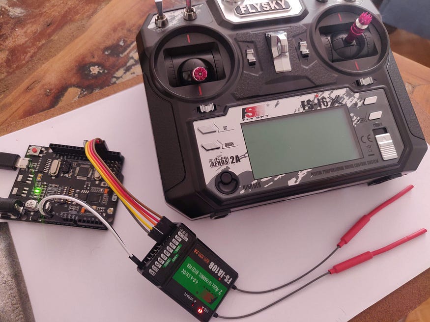
문제는 각종 센서나 ROS(ROBOT OPERATING SYSTEM)에서 처리한 정보에 근거해 PWM을 강제로 수정, 로봇 등을 제어해야할 때이다. 이 경우, 수신기와 아두이노 같은 임베디드 보드 GPIO를 연결해 PWM데이터를 얻어, 이를 수정한 후 PWM데이터로 출력해야 한다.
// title: MSR_RF2
// developed by: KTW
// date: 2020.11.5
#include <Servo.h>
#define CH1 2
#define CH2 3
#define CH3 4
#define CH4 5
#define CH5 6
Servo ESC1; // create servo object to control the ESC
Servo ESC2;
Servo ESC3;
Servo ESC4;
// Read the number of a given channel and convert to the range provided.
// If the channel is off, return the default value
int readChannel(int channelInput, int minLimit, int maxLimit, int defaultValue){
int ch = pulseIn(channelInput, HIGH, 30000);
if (ch < 100) return defaultValue;
return map(ch, 1000, 2000, minLimit, maxLimit);
}
// Red the channel and return a boolean value
bool redSwitch(byte channelInput, bool defaultValue){
int intDefaultValue = (defaultValue)? 100: 0;
int ch = readChannel(channelInput, 0, 100, intDefaultValue);
return (ch > 50);
}
void setup(){
Serial.begin(115200);
pinMode(CH1, INPUT);
pinMode(CH2, INPUT);
pinMode(CH3, INPUT);
pinMode(CH4, INPUT);
pinMode(CH5, INPUT);
ESC1.attach(8,1000,2000); // (pin, min pulse width, max pulse width in microseconds)
ESC2.attach(9,1000,2000);
ESC3.attach(10,1000,2000);
ESC4.attach(11,1000,2000);
}
int ch1Value, ch2Value, ch3Value, ch4Value;
bool ch5Value;
void loop() {
ch1Value = readChannel(CH1, 0, 180, 0);
ch2Value = readChannel(CH2, 0, 180, 0);
ch3Value = readChannel(CH3, 0, 180, 0);
ch4Value = readChannel(CH4, 0, 180, 0);
ch5Value = redSwitch(CH5, false);
Serial.print("Ch1: ");
Serial.print(ch1Value);
Serial.print(" Ch2: ");
Serial.print(ch2Value);
Serial.print(" Ch3: ");
Serial.print(ch3Value);
Serial.print(" Ch4: ");
Serial.print(ch4Value);
Serial.print(" Ch5: ");
Serial.println(ch5Value);
ESC1.write(ch1Value);
ESC2.write(ch2Value);
ESC3.write(ch3Value);
ESC4.write(ch4Value);
delay(500);
}
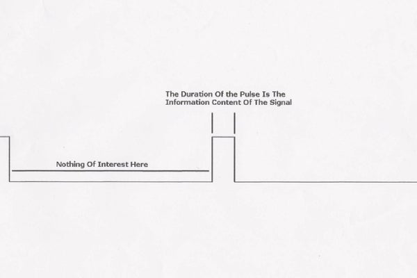
이제, 오실로스코프 두개 프로브에 각각 수신기 채널, 아두이노 출력 핀을 연결한다. 아두이노 수직 채널 입력 전압을 2V로 조정하고, 수평은 1.0 ms로 설정한다. 그리고, TRIGGER AUTO 버튼으로 시그널 수평을 고정한다. 그럼, 다음과 같이 입력후 처리된 PWM 진폭이 각각 일치하는 것을 확인할 수 있다.